So, although we’ve never had issues with our engine really running hot, it’s not been cool either. I’ve been a bit worried about it since our constant-speed prop will be shipping soon. With it, a much higher RPM will be available to us for climb-out, and with higher RPM comes higher engine horsepower. That’s all great, in fact, it’s a big part of why we’re getting the prop (the other that it helps create drag and steepen the landing approach), but it also means more heat from more air and fuel going into the engine to get burned to increase our acceleration.
Well, one of the things that isn’t in the manual (or at least wasn’t when I built my plenum), but universally done on Velocity’s is to augment the fiberglass plenum with metal cylinder base covers. This is especially important on the back of the engine (the end furthest from the prop) where the fiberglass can’t really get down to the cylinder bases because of the engine mount.
Luckily Jerry’s engine came with them already made, so I had a nice example of what others had done. These were made with tabs on both ends drilled for safety wire. The bottom has about two finger-widths of opening for cooling air, but otherwise forces the air across the cylinder heads for cooling. The top flange pushes against the fiberglass plenum to seal it, and the safety wire is looped around the inter-cylinder baffle arm to keep it from rotating. Even with this a fair amount of high temperature RTV and/or plates are needed to get a good seal. Dave Nelson and Ken Mishler (both of whom I have a great deal of respect for) have both told me that if you get a really good seal (no light shining out from around the edges) that your cooling will be fine. In fact, Ken stated recently that he got 60 degrees F CHT reduction from improving this sealing alone on a Velocity!
So, here is my attempt. Of course it’s cool out now, so we won’t really know what improvement I’ve gotten until next summer. Here are some pictures to show what I’m on about.

Plenum not quite against head |

Rear of engine, 1″ gap at cylinder base |

Same cylinder, gap shown from inside of plenum |
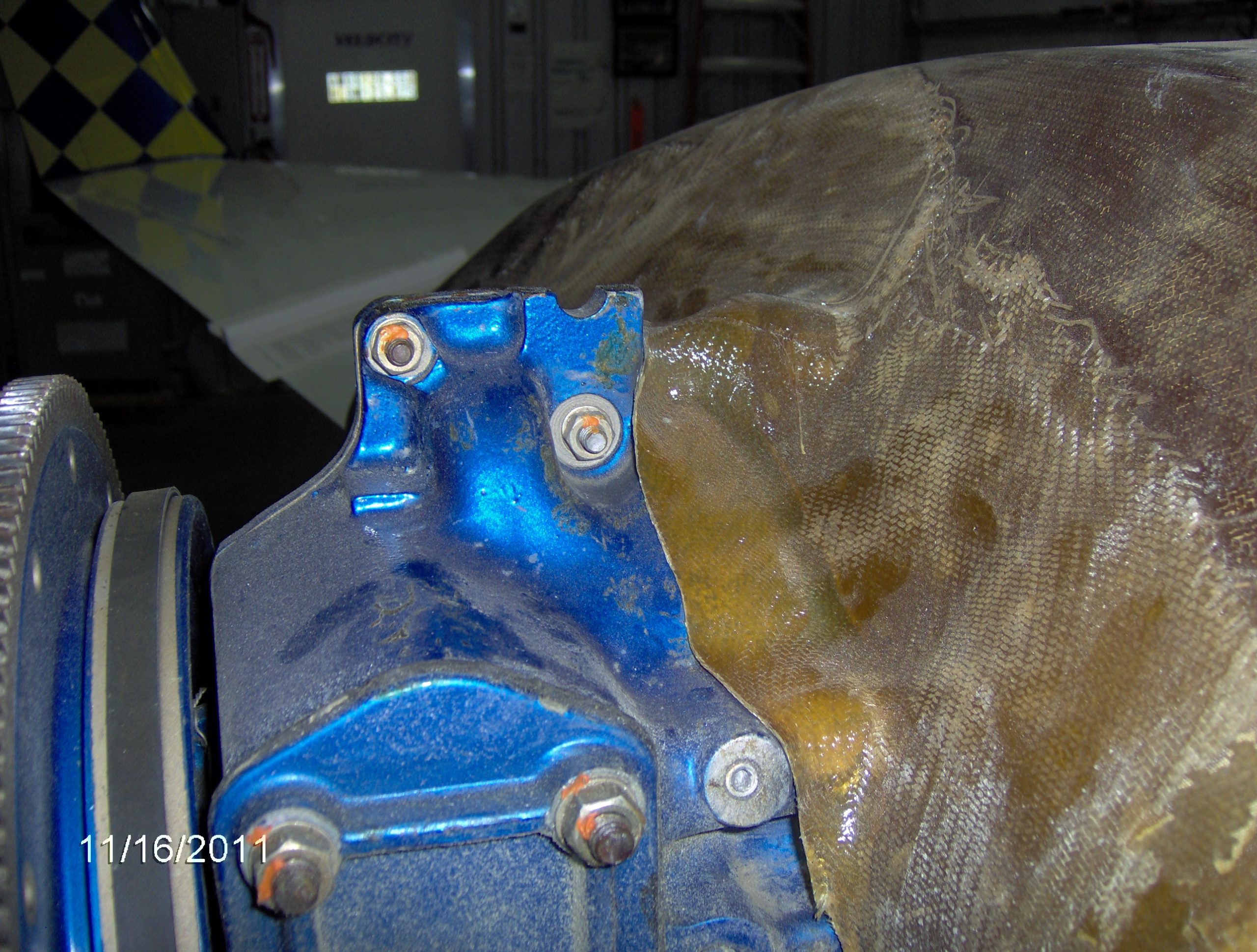
Front of engine, note the gap parallel to governor pad, we’ll seal this with RTV |

Same cylinder, see baffle sealing base |

This tab will be RTV’ed to front of engine/Lord Mount to seal cylinder base |

This is the cylinder closest to the governor pad, the plenum comes pretty far down here, the tab will seal against it |

This is the same cylinder from aft-on, showing how the baffle will seal (note I did straighten it up) |

This is a better view of the first picture, where you can see how much of the cylinder base is just open for the cooling air to bypass the fins |
|
Posted By: Brett FerrellSaturday November 19th, 2011 at 2:02 PM
[…] the cooling plenum modifications that I think I will need with the new prop. Read all about that here, but that is going well and should be in hand by the time the prop arrives. I should’ve done […]