Here is the basic electrical (power and ground distribution) system (as diagrammed at top of this chapter). First thing was to install the Ground Power and Master Solenoids, which both are rated for continuous duty, the instrument grounding block, and the battery. The master turns on the electrical power for the entire aircraft, except for the battery bus. The Battery Bus has one side of the electronic ignition system for the motor (in case we have an in-flight emergency requiring shutting the master off), the dome light, and the engine hour (Hobbs) meter.
Ground Power is pilot controlled, with a press to test button/light verifying that power is connected to the receptacle and is of the proper polarity. If so, closing a switch breaker allows all aircraft systems to be run off of the external power, the battery to be charged, or the engine to be jump-started.
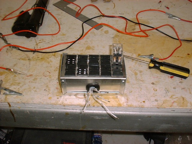
A relay box was created to handle two functions. First I didn’t want any high current in the overhead switch panel in the cockpit, so any high current application will be controlled by a relay where the switch only handles the low current in the cabin that drives the relay coil. Secondly, there are a couple of applications where we need to reverse the wiring, for the speed brake and pitch trim actuators, and we use relays for this application using both normally open and normally closed contactors. The relays are mounted all together in the nose of the airplane in quick-removal plugs for ease of maintenance. Also, the relay box itself was built with DB25 computer style connectors for quick installation or removal.
Continuing the electrical system installation, I’ve setup the Essential Bus diodes, seen in this first picture with the green leads. This will feed the avionics under normal circumstances from the main power bus, but is capable of being back fed from the the battery bus by switch on a switch-breaker on the instrument panel. This will allow the (all-electric!!) instrument panel to maintain basic flying requirements with the master off, in case of an in-flight emergency (electrical fire or alternator failure). The battery will happily support the Blue Mountain and the electronic ignition for more than an hour while a precautionary landing is made (not to mention the backup alternator installed on the vacuum pad). The diodes prevent the rest of the electrical system from being powered in this back-feed situation. Also note the many fuses that have been installed to support the operation systems, and the large cannon plug that will connect to the instrument panel. This will allow for the easy removal of both the panel and the canard wing.

Master and Ground Power Contactors |

Battery Installed |

Instrument Grounding Block |

Firewall Ground – Fore Side |

Firewall Ground – Aft Side / Starter Contactor |

Main Power Fuse Blocks |

Battery Bus Fuse Block |

Building Relay Box |
Installing Relays |

Contactors on Left, Essential Bus Diodes, and Battery Bus Fuses |

Wiring – Instrument Ground Above, Main Fuse Bus Near, Panel Plug on Top |
|
Posted By: Brett FerrellFriday December 12th, 2003 at 9:48 PM