The first thing we did in the avionics section was to install the headset and microphone jacks in the keel for all four passengers. Since I’ll be flying with Bose headsets, and will be including a four place intercom with music and DVD entertainment for the rear seat passengers, I installed stereo headset jacks (be careful if you want to do this, Spruce doesn’t sell them, and you’ll need to run 3-wire twisted pair for both headsets and microphone jacks).
We’ve purchased the PMA8000 audio panel/intercom from PS Engineering, which is a very nice stereo 6 place intercom with auto-squelch, a telephone and 2 entertainment inputs as the standard 2 comm inputs, it allows the pilot and co-pilot to operate the radios simultaneously, has a built-in marker beacon receiver, and a digital recorder for playing back ATC commands that you didn’t catch all of and the like.
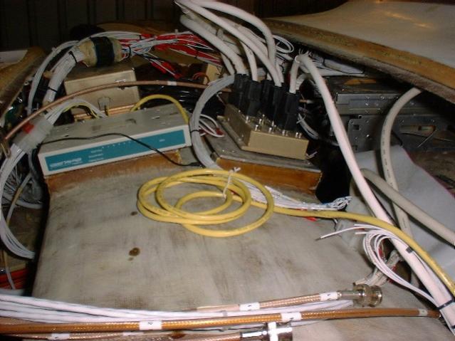
We’ve also purchased a ‘3 mode ELT’, the new style emergency locator transponder that broadcast to overhead satellites and can track your GPS and broadcast your last known position very accurately in case of a crash or hard landing. This Artex unit is very nice, with a 5G activation switch and antennas that we can mount internally. We’ll buy the NAV interface for the GPS signal later, but we needed the ELT to get our airworthiness certificate. Here also you can see our mounting location behind the ‘whale tail’ in the aft compartment. We’ve mounted it on an aluminum bracket next to the DVD player. This is the only position where it could be easily oriented properly (long axis longitudinal). Finally, the testing/arming switch is mounted on the instrument panel, and the activation warning horn is mounted behind it. The ELT antenna is installed a plate that’s permanently bonded with structure to the spar box to give it the best chance of surviving a crash.
Here you can see we’ve started the radio stack installation, even though we’ve not purchased all of the avionics yet. Here you can see we’ve affixed an ‘L’ bracket on the pilot side and a 1/4″ thick piece of AL bar stock to the co-pilot side where the cant is in the panel to mount the radio trays. We bought all of the trays, even though we couldn’t buy the electronics right now, so we could make a full-sized cutout and start fitting the trays in.
OK, so all of that non-sense about mounting the trays and the intercom never really worked for me. For one, I decided to go with the cheaper GTX327 transponder, which is an entirely different size than the mode-S (which is essentially obsolete with the new ADS-B system that will soon be implemented), and tapping the braces for the trays after they were attached to the panels was, shall we say, difficult to do accurately (not to mention try to get each of the boxes to line up square with just the instrument bezel sticking out). So, Jerry and I heated up the metal brace on the deep side and pulled it out, widened the hole and prepared to mount a thinner strip of aluminum on both sides (the bar I originally mounted there was easily twice what I needed). This allowed us to drill and tap the bars before installing, and mount them flush with the face of the tray, and the face of the panel (since the bars will be covered by the leather-wrapped cover later anyway, this will not pose a problem). It also allowed us to extend them down slightly to get the bigger transponder in without having to move the flash drive for the EFIS that was already mounted. I’ve also decided to go with the Approach Systems “Fast Stack” system, which greatly simplifies the interconnections between the radios and EFIS, etc. Here you see the grounded hardpoint I’ve cut to mount it to. This makes the radios almost as easy to installed as a home computer.
Later on, once the radios were ready to go in for good, a rear bracket was required. I took a piece of thin plate aluminum and drilled and tapped in to hold the aft end of the radio trays, and then cut a short section of L bracket aluminum to flox into the “roof” over the radios. This was also pre-drilled and tapped to match the rear bracket, and trough was cleared out in the roof for the angle. Once this would dry fit, I taped over the rear bracket, screwed the rear bracket to the L, filled the trough with flox, and installed the panel to hold everything in place until cured.
Here is a shot of the panel now, where I’ve mounted two jacks on it. One is for the cell phone interface to the intercom, the other for a aux entertainment input (MP3/iPod). The switch allows us to change from Aux to the Sirius satellite radio. Also, a switch at the base of the breaker panel allows us to listen to the rear entertainment source, the DVD/CD player, up front (it always feeds the rear passenger jacks).
We’ve now installed a used Apollo SL30 Navigation and Communications radio, a really nice unit, with a serial interface. This unit can be controlled by the EFIS/One (through our Approach wiring hub) so that when you bring up the airport in the flight planning page, it shows you the relevant frequencies, and you can select one to send to the radio directly. We’ve also installed a cabin speaker so we can hear, say the Automated Weather Service broadcast while sitting on the ramp loading the plane. Other nice system integration features that we just tested,
- Comm 1/Comm 2 swap on the joystick swaps the audio panel selection
- BMA EFIS/One outputs transponder Pressure Altitude grey code to GTX327
- Button on joystick activates the pilot PTT “Warren County, 4-Victor-Fox, Radio Check”… “4-Victor-Fox, read you loud and clear”
- Co-Pilot PTT on right side panel
- Button on joystick activates the PMA8000 “digital playback” of last few transmissions, one per button click, to re-hear ATC clearances, etc.

Intercom Panels Fitted |

Intercom Panels with Headset/Microphone Jacks Installed |

PS Engineering PMA8000 |

Artex G406 |

ELT Mounting Hole in Whale-Tail |
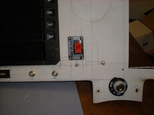
ELT Arming Switch |

ELT Warning Buzzer |

ELT Antenna Installed Behind “False” Rear Bulkhead |

From Co-Pilot Side |

From Pilot Side |
| https://velocityxl.bdfserver.com/wp-content/uploads/2020/05/Radio_Tray_Fitting.jpg
Test Fitting the Trays |

Fitting the Intercom |

Radio Trays |

Mounting Radio Trays (note bar stock on both ends) |

Approach Hub |

Hub Mounting Base |

Hub Mounting Plate / Ground Plane |

Rear Radio ‘L’ bracket with flox |

Rear Radio Bracket (with duct tape) attached to floxed ‘L’ Bracket |

Sirius Satellite Radio and Aux/Cellular inputs |

Installing the Apollo SL30 NAV/Comm |
Network Hub for Autopilot and ApproachAvionics Hub System Installed on Canard |
Posted By: Brett FerrellWednesday May 12th, 2004 at 10:43 PM
[…] work continues with headset/microphone jack installation, nose oil tubing installed, aileron cables pulled through firewall, and seat heater switches […]
[…] and work concerns, but we’re back up to speed now. Currently working on installing the intercom and the engine, including mocking-up the exhaust for […]
[…] ELT installation proceeding, preparing for Oshkosh… Catto prop due after Oshkosh along with our move to the airport! Engine Controls installed, and oil door completed, and spinner fitting started. […]
[…] I got the audio panel preliminarily wired up last night (long holiday weekend), and it is simply awesome to plug in a headset and talk into […]
[…] completed (for now, it’ll need final paint with everything else later), radio trays installed and intercomm and transponder mounted-wiring beginning, and still chasing various engine bugs […]